MORGAN RC
A division of www.morganmill.com

Specifications:
6mm MPF Construction
Single Motor 2212-6
30" Wingspan
30" Length
18oz. AUW
4 channel Elevator, Aileron, Rudder, Throt. Servos - HXT-900
Battery - 1300mah 3s
1- APC 6x4
6mm MPF Construction
Single Motor 2212-6
30" Wingspan
30" Length
18oz. AUW
4 channel Elevator, Aileron, Rudder, Throt. Servos - HXT-900
Battery - 1300mah 3s
1- APC 6x4
Made in the USA

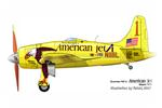
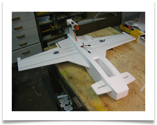
Ocelot Flying Boat
The Ocelot kit was developed the over the last 3 years as part of my ongoing facination with flying off of water.
The airframe was created as a high performance flying boat that has aerobatic capability as well as a fantastic slow flight envelope.
It's named after a cat that likes water.
Snap rolls, Knife edge flight, Tumbles , Hammer Heads, Rolling Circles, Inverted flight, Flat Spins. Along with superb water and ground handling.
It's at home on grass, snow and of course water!
Status: Production version is Airborne!
What's included in the kit:
All Laser Cut 6mm Model Plane Foam airframe parts.
2 - 1x5x1000mm Carbon Fiber Spars
4 - Vacuum formed servo covers.
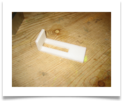
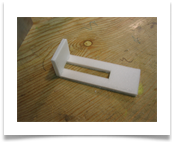
1- Hatch tongue
2 - Servo Rings Mounts
1- 1/8" Ply Fire Wall
1- 1/8" Firewall Backer
4 - Control horns
2 - Air Scoops - Intake and Exhaust
All Laser Cut 6mm Model Plane Foam airframe parts.
2 - 1x5x1000mm Carbon Fiber Spars
4 - Vacuum formed servo covers.
1- Hatch tongue
2 - Servo Rings Mounts
1- 1/8" Ply Fire Wall
1- 1/8" Firewall Backer
4 - Control horns
2 - Air Scoops - Intake and Exhaust
What you will need to complete:
Motors 1x 2212-6
1 - 30-40 amp ESC
1- APC 6x4 Prop
1- 1300mah 3s lipo
4 - HXT 9 gram Servos
2- Magnets for Hatch
1mm Servo Control Rods
14 Guage - Motor Power Wire
Beacon Foam Tac Glue
2 square yards of .75oz fiber glass cloth
3-4oz Minwax Polycrylic (WBPU)
Motors 1x 2212-6
1 - 30-40 amp ESC
1- APC 6x4 Prop
1- 1300mah 3s lipo
4 - HXT 9 gram Servos
2- Magnets for Hatch
1mm Servo Control Rods
14 Guage - Motor Power Wire
Beacon Foam Tac Glue
2 square yards of .75oz fiber glass cloth
3-4oz Minwax Polycrylic (WBPU)
Build Instructions:
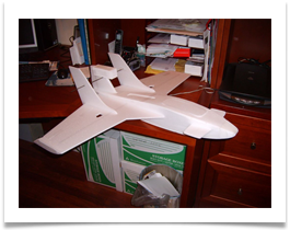
Original Prototype 2009
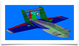
Original Computer Aided Design 2009
Ocelot
Flying Boat
Kit
$79.95
Flying Boat
Kit
$79.95
#2 Nacelle Construction:
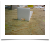
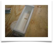
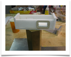
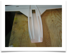
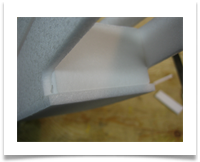
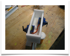
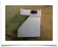
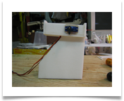
Glue together pieces shown making sure to achieve the angle shown against the square (image 8353) as the motor incidence is fairly critical in this aricraft. The side walls of the motor nacell are cut at a slight angle.
The elevator servo is on the right side of the necelle with the firewall forward or towards the bow - rudder on the left.
Suggested tools and glues:
Push Pins
#11 Exacto Knife
Foam Tac or Hot glue
Fabric cutter wheel for FG Cloth (Works Great!)
Push Pins
#11 Exacto Knife
Foam Tac or Hot glue
Fabric cutter wheel for FG Cloth (Works Great!)
#1 Wing & Carnard Spars - Glassing:
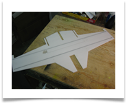
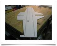
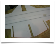
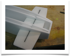
For stated maximum performance it is required that you glass both sides of the foam sheets with .75oz. fiberglass cloth and a coat of Minwax Polycrylic (WBPU). This has the effect of making all the parts much more resistant to hanger rash and giving the aircraft an incredible amount of rigidity.
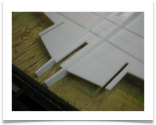
Cut the supplied carbon fiber spars to length matching the cut slots in the foam.
Glue 1x5mm carbon spars into the wing and canard, then glass both sheets on both sides as the first step before you remove the parts from the full sheet.
Cut a 24"x36" piece of cloth and lay it over the foam on a clean flat surface - with a foam paint brush create/impart a static charge to the FG cloth by dry brushing the cloth to the foam from the center outward. This helps keep the cloth in place while you brush on the polycrylic also from the center outward. Try to complete this in one coat.
Do not remove any parts from the full sheets yet - spar and glass them first!!!
#3 Nacelle to Pylon Connection:
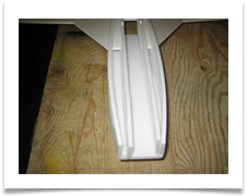
Laminate the 2 piece pylon together making sure edges are flush with each other.
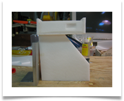
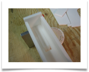
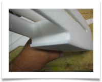
Glue pieces shown making sure to achieve the angle shown against the square (image 8354).
The pylon is marked with a "T" indicating the top and an arrow indicating forward or bow. This arrow will be hidden below the top deck once the pylon is glued in the hull.
The pylons top edge is flush with the bottom of the nacelle floor leaving a small gap forward - this is for the servo wires leading forward under the wire shield supplied.
#4 Rudder:
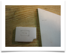
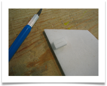
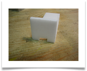
Remove the 1/2"x3/4" rectangle of foam from the sheet and glue a supplied control horn into the slot provided on the rectangle. Glue the rectangle and horn composite to the rudder panel matching the slot angle on the rudder. (Note - this is different than the pictures below as the control rod and horn will now clear the back of the motor nacelle when actuated by the servo).
Remove the 1/2"x3/4" rectangle of foam from the sheet and glue a supplied control horn into the slot provided on the rectangle. Glue the rectangle and horn composite to the rudder panel matching the slot angle on the rudder. (Note - this is different than the pictures below as the control rod and horn will now clear the back of the motor nacelle when actuated by the servo).
Glue the elevator and rudder servo rings supplied to the sides of the nacelle.
#5 Fuselage & Hull bottom:
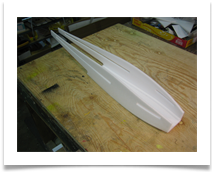
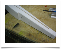
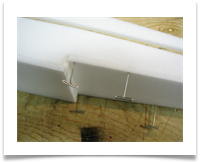
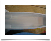
Glue the fuse sides on top of the hull bottom - the use of push pins here is recommended.
Then glue the joint doublers as shown - a little extra glue during this step will have water proofing benifits.
Glue the fuse sides on top of the hull bottom - the use of push pins here is recommended.
Then glue the joint doublers as shown - a little extra glue during this step will have water proofing benifits.
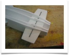
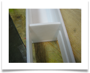
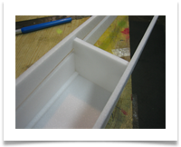
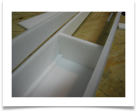
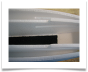
Temporarily place the wing into the fuse/hull to get a feel for how things are fitting together. Place the fuse bulkheads into position noting they are larger and not cut to finish size at this point - this is beacuse every build is slightly differnt due to glue conditions etc.
Cut the bulkheads to fit your hull and glue them into place.
Cut the bulkheads to fit your hull and glue them into place.
#6 Aft Hull :
Glue the aft hull piece to the bottom of the fuse sides - the use of push pins here is recommended.
A little extra glue during this step will have water proofing benifits.
Please note - a small recess is formed at the step of the hull when all the pieces come together at this point - this is to introduce air at the step so the hull can let go of the water a little eaiser.
#7 Fuse & Wing:
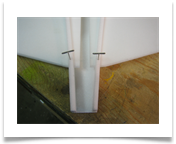
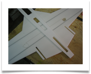
To give yourself a guide for placement of fuse on the wing - lay the top deck on the wing - get it positioned by aliging the slot for the pylon and the front edge of the wing and fuse joint. Place a couple of push pins to secure temporarily - do this on both top and bottom of the wing with the top deck. Mark with a pen.
To give yourself a guide for placement of fuse on the wing - lay the top deck on the wing - get it positioned by aliging the slot for the pylon and the front edge of the wing and fuse joint. Place a couple of push pins to secure temporarily - do this on both top and bottom of the wing with the top deck. Mark with a pen.
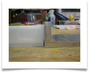
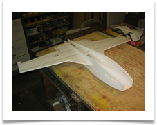
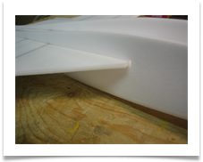
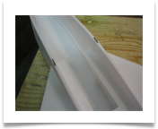
Then remove and glue the fuse to the wing as shown using your pen line. Please note - you will have to make sure the fuse side wall is flush with the corner of the wing to avoid the example in pic. 8372.
#8 Interior Bulkheads:
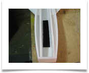
Repeat the procedure for placement of the interior bulkheads mark there location and glue into place.
Use the canard for placement of bulkheads as an aid for alignment. Please note - you may need to cut a little off the length of the bulkhead at the aft end against the step bulkhead.
Repeat the procedure for placement of the interior bulkheads mark there location and glue into place.
Use the canard for placement of bulkheads as an aid for alignment. Please note - you may need to cut a little off the length of the bulkhead at the aft end against the step bulkhead.
Install the canard and bow bulkhead.
#9 Hatch Support Rings:
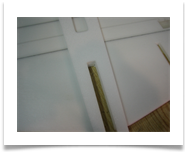
At this point it's best install magnets for battery hatch then install the hatch ring in the recess in the interior bulkheads - this is to provide a base for the battery hatch. The aft hatch ring glues to the bottom of the top deck centered under the hole. The aft hatch is meant to be taped in place for future service access to your ESC and reciever area. Glue the forward hatch tongue (plywood) to the bottom of the forward hatch - this slips in between the hatch ring and the top deck in a slot created in the glue joint with a knife .
At this point it's best install magnets for battery hatch then install the hatch ring in the recess in the interior bulkheads - this is to provide a base for the battery hatch. The aft hatch ring glues to the bottom of the top deck centered under the hole. The aft hatch is meant to be taped in place for future service access to your ESC and reciever area. Glue the forward hatch tongue (plywood) to the bottom of the forward hatch - this slips in between the hatch ring and the top deck in a slot created in the glue joint with a knife .
#11 Top Deck & Pylon:
At this point it might be a good idea to pour a quarter to a half a cup of water in your fuse to checkfor water tight integrity.
Glue the top deck in position after you have decided the placement of all your wiring and equipment placement. Glue the nacelle and pylon into the fuse and top deck. Use of push pins in recommended.
#13 Elevator and horizontal stabilizer:
Install the elevator on the horizontal stab. Then install the assembly into the vertical stabs.
Install the elevator on the horizontal stab. Then install the assembly into the vertical stabs.
#14 Rudder:
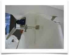
Install the rudder, control rod, control rod connector and horn as shown.
Install the rudder, control rod, control rod connector and horn as shown.
#12 Aileron & Aileron Servos:
Hot glue
Glue the aileron servos flush to the top of the wing and run the wires into the fuse in the slots provided.
It is recommed that you use hot glue for this step as hot glue can be de-bonded with alcohol - so you can service the servo in the future if necessary. Glue the bottom servo covers on after you test fit. The top servo covers are one of the last steps prior to completion.
Install the Ailerons with CA hinges and foam safe CA or the glue of your choice - I like to use foam-tac with CA hinges as the joint is a little more supple.
#11 Vertical & Horizontal Stabilizer:
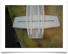
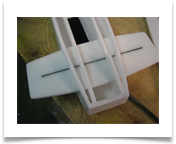
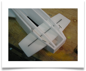
Install the vertical stabilizers in the slots in the rear of the wing. The correct angle for the vertical stabs. is achieved by the using the length of the horizontal stabilizer snapped into the slots in the vertical stabs. Glue horizontal stab. to top of nacelle and joints in vertical stabs. Make sure parts are even with your eye and glue into place. Tape or pin into finish position.
Install the vertical stabilizers in the slots in the rear of the wing. The correct angle for the vertical stabs. is achieved by the using the length of the horizontal stabilizer snapped into the slots in the vertical stabs. Glue horizontal stab. to top of nacelle and joints in vertical stabs. Make sure parts are even with your eye and glue into place. Tape or pin into finish position.
#10 Rudder & Elevator Servos:
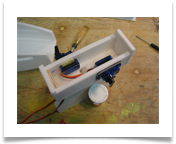
Screw the rudder and elevator servos into the sevo ring on the nacelle and test for correct function.
Screw the rudder and elevator servos into the sevo ring on the nacelle and test for correct function.
